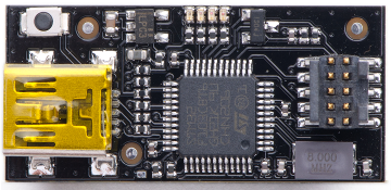
ARM Cortex M0+ Atmel SAM D20 E
The board is centred around the Atmel SAM D20 microcontroller. We use the smallest E variant in a QFN-32 package (-M)
The firmware is written in C and can be built using GNU Tools for ARM Embedded Processors See README-samd20-gcc-blackmagic.md for more details.
From the datasheet we can see there’s a few RAM/ROM size options:
| -14 | 16 KBytes | 2 KBytes |
| -15 | 32 KBytes | 4 KBytes |
| -16 | 64 KBytes | 8 KBytes |
| -17 | 128 KBytes | 16 KBytes |
| -18 | 256 KBytes | 32 KBytes |
We’ve been using the -17 variant so far, but may upgrade to the -18 variant if we need more Flash for geofencing or SRAM for backlog.
The SAM D series implements Generic Clocks (GCLKs) which allow us to divide, route and disable clock signals internally as required. These are used particularly for APRS.
Thanks to an error in Revision C silicon we can’t configure the correct pin layout for the SERCOM used to talk to the radio. Currently it’s just being bit-banged as both Mouser and Farnell appear to have bought large quantities of Revision C silicon. TODO: Fix in future board revision??
Global Positioning System ublox MAX-M8C
The MAX-M8C module is used for positioning. The -M8C variant has a 1.65V - 3.6V supply but doesn’t include a RTC crystal. The ARM Cortex communicates over 9600 baud UART using the UBX protocol.
The module is set in flight mode (Platform Model = AIRBOURNE
1G). Whilst the module is capable of receiving two GNSS contellations
at once it is set to only receive GPS. This allows the receiver to be
set in power save mode (lpMode = 1 in the CFG RXM
message). TODO: Update this after experiments with advanced
powersave modes
HAB Supplies is a great supplier for this module.
TODO: Photo
Radio Si 4063/60
The tracker uses the Si4063/60 transmitter from Si-Labs, although the Si446x series of transceivers is pin-compatible. With a 1.8V - 3.6V supply and 142 - 1050MHz frequency range this transmitter is ideal.
The Si4060 specifies a max output power of +13dBm, and the Si4063 specifies +20dBm. Thus far we have used the Si4063 on a reduced power setting to give +6dBm of output power as measured by a signal analyser. TODO: More testing to bring the output power up to the +10dBm limit.
For FSK modes (RTTY, Contestia) the radio is set in CW mode and the
MODEM_FREQ_OFFSET parameter is used to set the tone. The 16.369MHz
clock from the TCXO gives a frequency resolution of 7.8053 Hz in this
case.
For AFSK (APRS) the radio is set in 2GFSK mode and the
MODEM_FREQ_DEV parameter is used to set the FM deviation. GPIO1 is
then used in direct mode as a modulation input. The radio applies a
gaussian filter to this square wave which results in an acceptable
spectrum. See this ipython notebook for more details on how the
MODEM_TX_NCO_MODE parameters are chosen et cetera. (The internal
filter is a 17-tap FIR filter that is by default configured as
gaussian.)
Debugging
To program and debug the ARM Cortex we use a Blackmagic Probe. The probe and its source are GPL-licensed and available in the github repository.
You can build your own or buy one online.
Memory 128Mbit SPI Flash
This hasn’t been used for anything yet, and we haven’t even written the drivers. Potentially could be used in future?
Sometimes we don’t populate this.
Here’s the datasheet.
16.369MHz TCXO
We use a temperature controlled oscillator (TXCO) from Epson to provide a clock to both the radio and ARM Cortex.
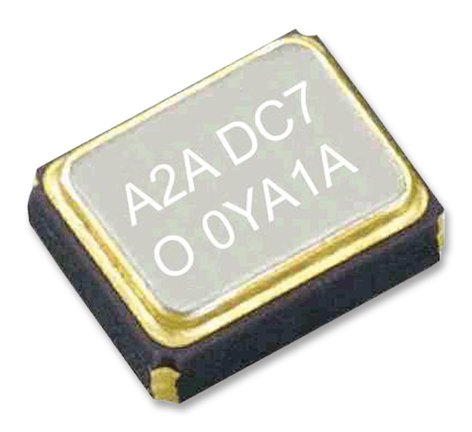
The Pin 1 marker is a perfect circle.
It has a supply voltage of 1.7V - 3.3V. This was one of the harder
parts for find for a 1.8V volt supply. The output waveform is
specified at 0.8Vpk-pk and in test it’s about 0.9Vpk-pk. This is no problem
for the radio but ideally would be higher for the CLKIN pin of the ARM
Cortex. We’ve had no problems with a 1.8V supply, but at 3.3V the ARM
Cortex never locks on the clock. In this case the
USE_XOSC option in firmware can be set false.
The frequency tolerance is given at ±2 parts-per-million (ppm) at 25°C, with ±1 ppm per year aging at 25°C. The temperature range is given at -30°C to 85°C with another ±2 ppm variation over this range. We’ve tested it to -55°C by dropping it unprotected into the jet stream (as you do) and it got rather drifty (10 ppm??) before the board cut out. TODO: Cold chamber testing
GPS Antenna
A 1/4 wave piece of guitar wire is used for the GPS antenna. This has vertical polarisation which means it will be 3dB down compared to a right-hand circularly polarised antenna. However the antenna has such a clear view of the sky that this isn’t an issue. TODO: Good picture
Telemetry Antenna
The telemetry antenna is a 1/4 wave ground plane antenna that is tuned to 434 MHz. It’s built from guitar wire with little bits of kapton tape on the end.
TODO How does this perform on 2 meters for APRS?
TODO: Photo
Hardware Watchdog
Windowed Hardware Watchdog
Radio Filter
5th order Chebyshev

RTTY U8N2
The tracker transmits Radio Teletype (RTTY).
Contestia 32/1000
The tracker alternately transmits Contestia Mode.
APRS
The tracker also transmits Automatic Packet Reporting System (APRS) packets.
Geofence
The tracker uses geofences to decide which frequencies to operate on etc. APRS transmissions essentially follow this map and this list with exceptions for areas where airboune operation is not permitted.
See this ipython notebook used to automatically generate the C header files used for geofencing.
TODO: Actually test this